| .forgejo/workflows | ||
| case | ||
| esp | ||
| brightness.png | ||
| photo.jpg | ||
| README.md | ||
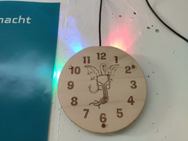
Ambient Lighting Clock
3D model and ESP8266 code for a clock that projects colorful rays of light against the wall:
- Hours: Wide red
- Minutes: Blueish green
- Seconds: Blue
Enclosure
The directory case contains the OpenSCAD project and rendered STL file of the clock's enclosure for 3D printing.
The enclosure is designed to be 3D-printed, and fits an 60x WS2812 LEDs strip with 144 LEDs per meter, such as this one (AliExpress link)
The enclosure also contains mounting holes to which a front plate can be attached (such as in the photo above). To create your own clockface with a laser cutter, use the file clockface.svg for cutting, and add your own digits and other decoration as an engraving layer.
ESP8266
At the heart of the clock sits an ESP8266, which connects to a WiFi network and fetches the current time of day via NTP.
To build the code and program the ESP, you need to install the PlatformIO framework.
The WS2812 data line needs to be connected to the ESP's GPIO5 pin. Note: Most breakout boards define their own pin numbers. For example, with a NodeMCU, GPIO5 corresponds to pin D1.
$ git clone https://git.kabelsalat.ch/s3lph/ambient-lighting-clock.git
$ cd ambient-lighting-clock/esp
$ vim src/main.cpp  # Insert the WiFi SSID and PSK
$ pio run  # To download dependencies and build without programming the ESP
Processing main (platform: espressif8266; board: nodemcu; framework: arduino)
--------------------------------------------------------------------------------------------------------------------------------------
Verbose mode can be enabled via `-v, --verbose` option
CONFIGURATION: https://docs.platformio.org/page/boards/espressif8266/nodemcu.html
PLATFORM: Espressif 8266 (2023.4.0) > NodeMCU 0.9 (ESP-12 Module)
HARDWARE: ESP8266 80MHz, 80KB RAM, 4MB Flash
PACKAGES:
 - framework-arduinoespressif8266 @ 2.7.4+9
 - tool-esptoolpy @ 1.40501.0 (4.5.1)
 - toolchain-xtensa @ 2.40802.200502 (4.8.2)
LDF: Library Dependency Finder -> https://bit.ly/configure-pio-ldf
LDF Modes: Finder ~ chain, Compatibility ~ soft
Found 31 compatible libraries
Scanning dependencies...
Dependency Graph
|-- Adafruit NeoPixel @ 1.11.0
|-- NTP @ 1.6.0
|-- ESP8266WiFi @ 1.0
Building in release mode
Retrieving maximum program size .pio/build/main/firmware.elf
Checking size .pio/build/main/firmware.elf
Advanced Memory Usage is available via "PlatformIO Home > Project Inspect"
RAM:   [====      ]  35.4% (used 28984 bytes from 81920 bytes)
Flash: [===       ]  26.8% (used 279396 bytes from 1044464 bytes)
==================================================== [SUCCESS] Took 1.58 seconds ====================================================
$ pio run -t upload  # To build the code and program it to the ESP8266
Configuring upload protocol...
AVAILABLE: espota, esptool
CURRENT: upload_protocol = esptool
Looking for upload port...
Auto-detected: /dev/ttyUSB0
Uploading .pio/build/main/firmware.bin
esptool.py v4.6-dev
Serial port /dev/ttyUSB0
Connecting....
Chip is ESP8266EX
Features: WiFi
Crystal is 26MHz
MAC: 2c:3a:e8:01:23:45
Uploading stub...
Running stub...
Stub running...
Configuring flash size...
Flash will be erased from 0x00000000 to 0x00045fff...
Compressed 283552 bytes to 208462...
Writing at 0x00000000... (7 %)
Writing at 0x00005b34... (15 %)
Writing at 0x0000b2c4... (23 %)
Writing at 0x00010670... (30 %)
Writing at 0x00015f2e... (38 %)
Writing at 0x0001b0d0... (46 %)
Writing at 0x000200a6... (53 %)
Writing at 0x0002523e... (61 %)
Writing at 0x0002a761... (69 %)
Writing at 0x0002fcd8... (76 %)
Writing at 0x00035551... (84 %)
Writing at 0x0003ac1f... (92 %)
Writing at 0x00041169... (100 %)
Wrote 283552 bytes (208462 compressed) at 0x00000000 in 18.3 seconds (effective 124.1 kbit/s)...
Hash of data verified.

Leaving...
Hard resetting via RTS pin...
=================================================== [SUCCESS] Took 23.76 seconds ====================================================
Automatic Brightness Adjustment
You can attach a voltage divider with a photo resistor as pull-down and a regular resistor as pull-up to the ESP's8266 ADC. If you choose to do this, please check the ADC voltage level of your ESP8266 board: While the ADC itself works in the range 0.0V...1.0V, a lot of breakout boards scale that up to 0.0V...3.3V.
Example with a NodeMCU board:
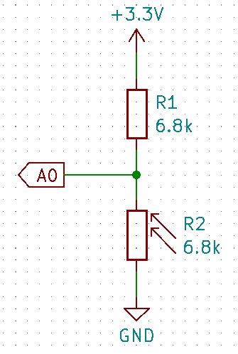
You can use the values ADC_MAX, ADC_MIN, BRIGHT_MIN and BRIGHT_MAX at the top of the file esp/src/main.cpp to fine-tune the sensitivity and thresholds of the auto adjustment.
If you do not use this feature, and observe some flickering, please short the ADC to GND.