Remote control the CCC Basel video projector via MQTT ( -> ESP8266 -> RS232 -> projector )
| .forgejo/workflows | ||
| esp | ||
| pcb | ||
| README.md | ||
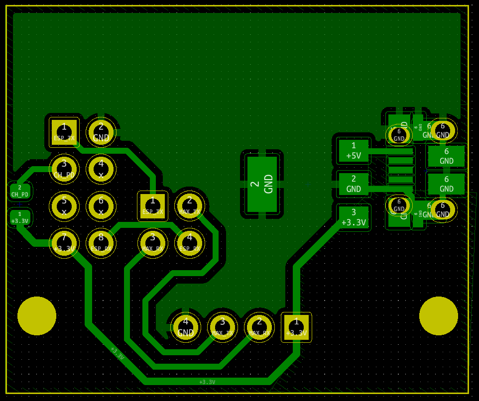
| screenshot.png | ||
Remote control the CCC Basel video projector via MQTT ( -> ESP8266 -> RS232 -> projector ).
This repo contains
- A PlatformIO project for an ESP8266 firmware which connects to an MQTT server and subscribes to certain command topics
- A KiCad project for an adapter and power supply PCB which connects an ESP-01 to a MAX3232 board and provides power to both from a USB Micro-B socket.
ESP8266 Firmware
Building
Edit esp/src/main.cpp and set the configuration (WiFi credentials, MQTT broker & topic)!
For Sanyo Z4:
cd esp
pio run -e sanyoz4 -t upload --upload-port /dev/tty<X>
For Benq X3000i
cd esp
pio run -e benqx3000i -t upload --upload-port /dev/tty<X>
PCB
BOM
- ESP-01
- A MAX3232 + D-Sub 9 connector board
- The adapter PCB is designed for this specific MAX3232-Board from AliExpress
- 1x 10k 0805 SMD Resistor
- 1x 2x2 2.54mm pin header
- 1x 2x4 2.54mm socket header
- 1x 1x4 2.54mm socket header
- 2x 2.54mm jumpers
- USB Micro-B socket
- SOT-223 3v3 voltage regulator
The USB socket footprint in this PCB is modified to use circular holes, because our PCB mill can't mill oval holes that small. If your chosen USB socket has thru-hole legs wider than 1mm, you may want to replace the footprint with another one from KiCad's library.
Assembly
- The copper side (bottom) faces the MAX3232 board, with the 1x4 socket header plugged into the matching in header on the MAX3232 board.
- The 2x4 socket header faces the other direction, this is where the ESP-01 is plugged into
- The 2x2 in header can face either direction (if facing down, check beforehand whether there's enough space to the MAX3232 board
- The jumpers go next to each other on the 2x2 pin header. Depending on their orientation, Rx and Tx can be swapped if necessary.