| images | ||
| .gitignore | ||
| case.scad | ||
| key_dial.scad | ||
| lockpuzzle.scad | ||
| plug.scad | ||
| README.md | ||
| render.sh | ||
| ring.scad | ||
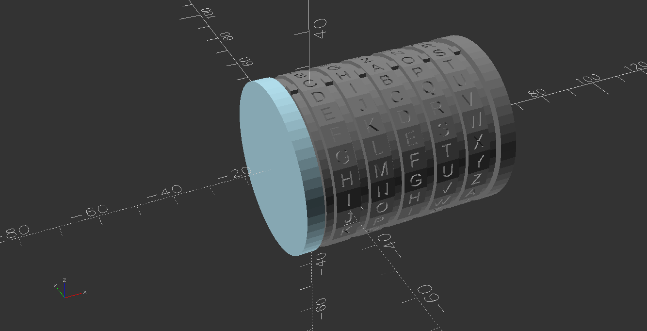
Lock Puzzle
A 3D-printed puzzle box written in OpenSCAD.
Usage
Rendering
- Make sure you have OpenSCAD installed.
- In the file
render.sh, change at least theLENGTHvariable to the length of your chosen password.- You can also change other settings such as the alphabet, or the diameter of the box.
- The default diameter (and the one the printed model has been tested with) is 50mm. The lock mechanism takes 20mm off this, so the inner diameter is 30mm.
- The length of the box currently depends on the length of the password, and is
(LENGTH*10+15)mm. The length of the inner space is(LENGTH*10)mm.
- Run
./render.sh, which will create all the STL files you'll need in theout/directory.- If you are using an OpenSCAD version without support for the Manifold rendering engine, remove the
--backend=manifoldargument.
- If you are using an OpenSCAD version without support for the Manifold rendering engine, remove the
3D Printing
Print the following objects:
- 1 x
case.stl - 1 x
plug.stl - 1 x
key_dial_${character}.stlfor every character in your password. - LENGTH x
ring_click.stl - 1 x
ring.stl
Assembly
-
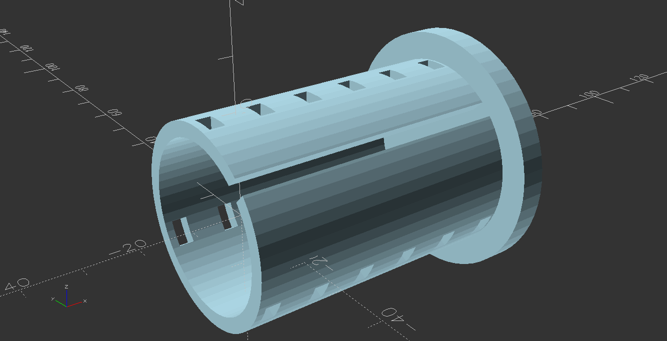
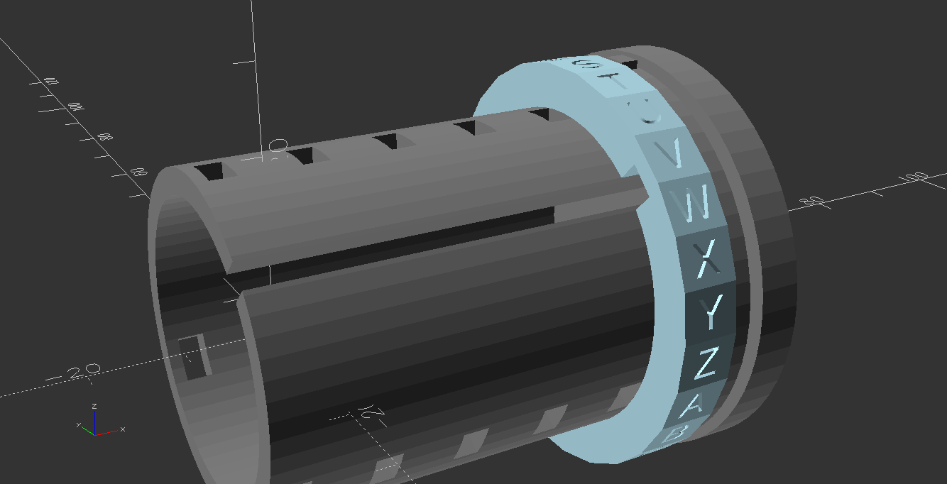
Start with the printed case:
-
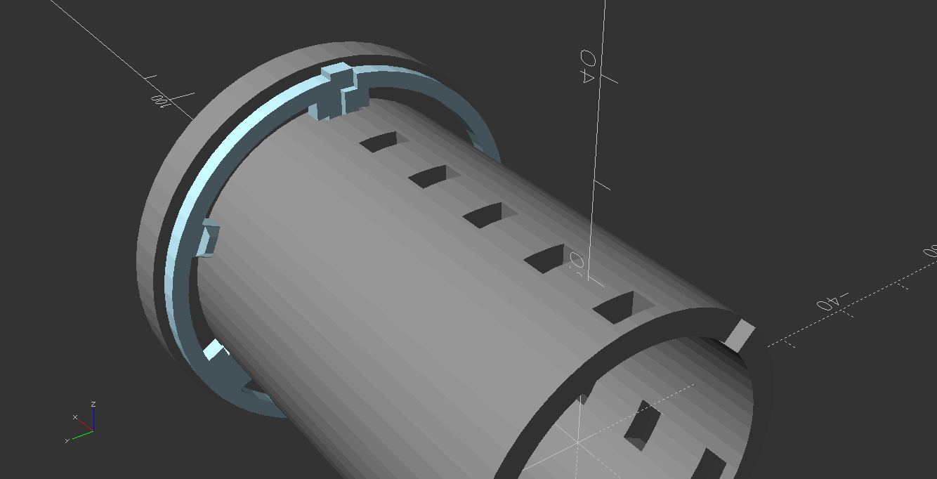
Add the first ring to the case as shown here. Note that the outward-pointing position indicator and the sideways-pointing "clicker" must be oriented exactly as shown here:
-
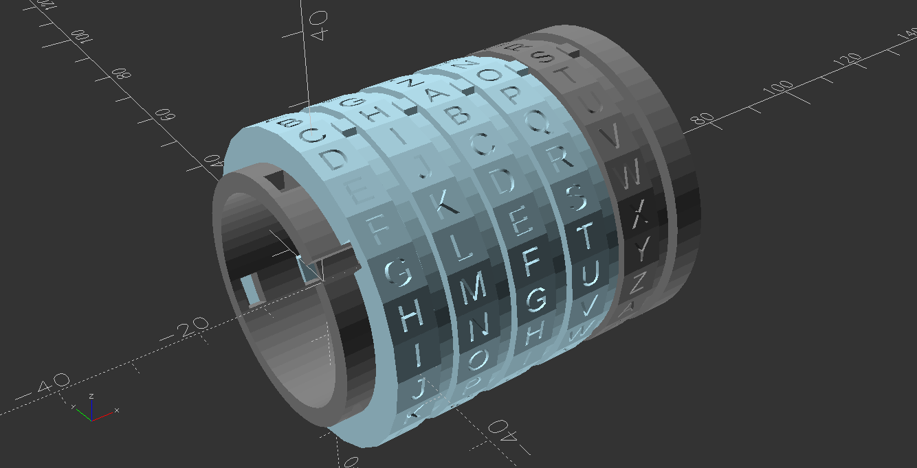
Add the first dial case as shown here.
-
Repeat steps 2 and 3 until you reach the last dial.
-
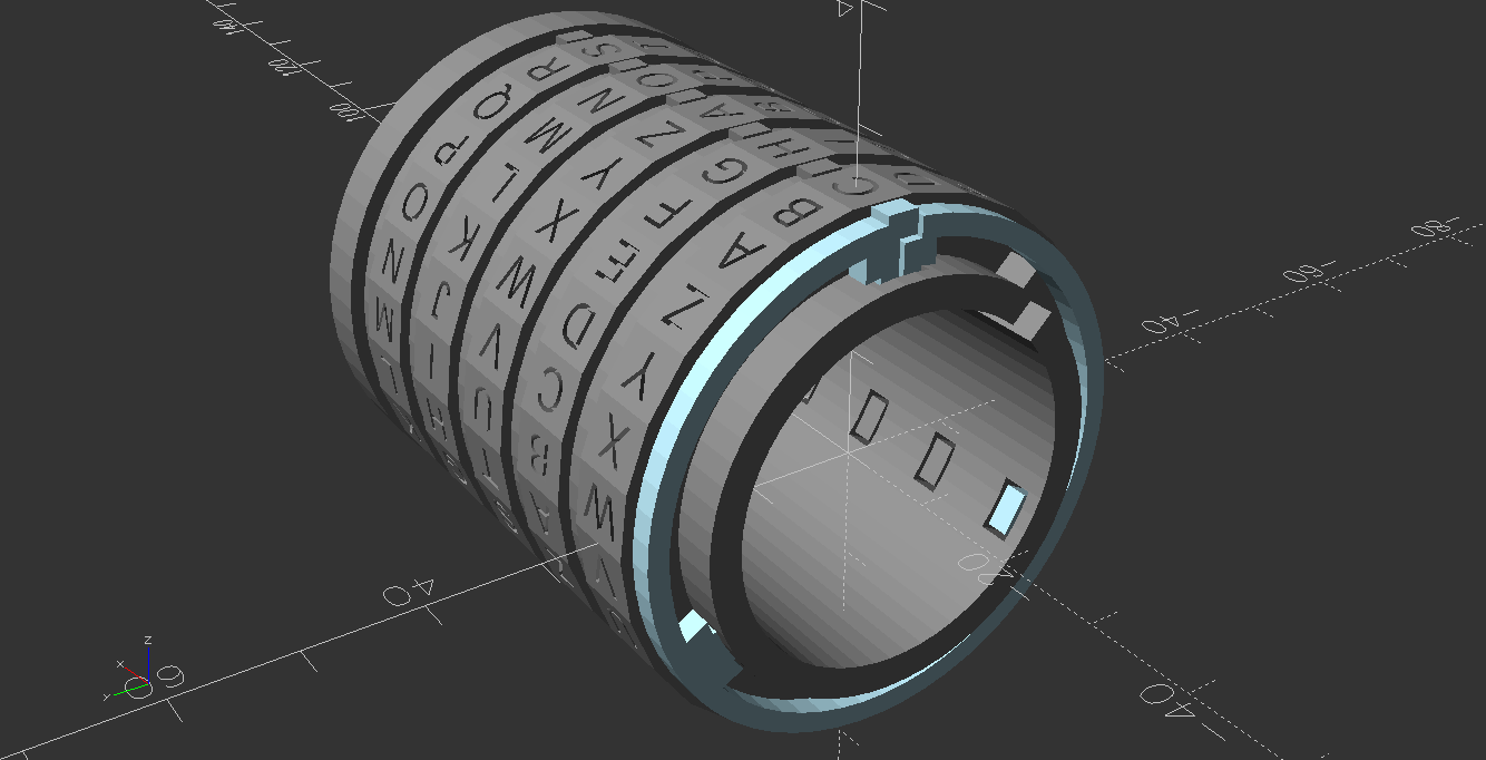
Add the final ring to the case as shown here. Note the absence of the clicker.
-
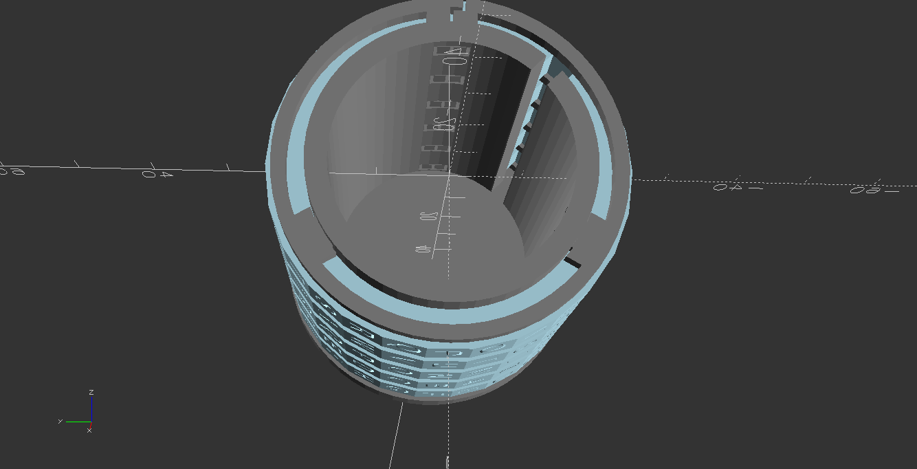
Turn all dials so that the cutout lines up with the long slot in the case. Turning the dials might require quite some force at first, but after a few turns the clicker will wear down a bit, which will make the dials easier to turn.
-
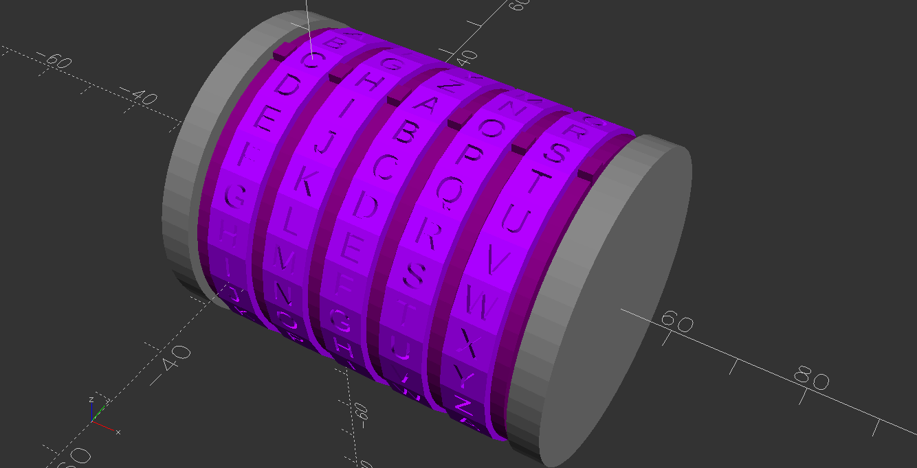
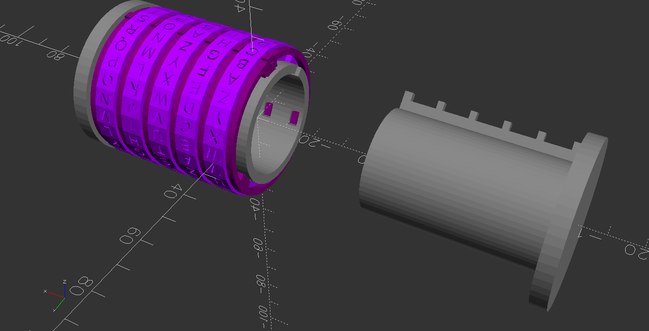
Finally, insert the plug all the way, then turn the dials to lock the puzzle box:
