| erfamap-output | ||
| esp32 | ||
| images | ||
| led_plugging_tool | ||
| pcb | ||
| LICENSE | ||
| README.md | ||
SpaceAPI LED Map
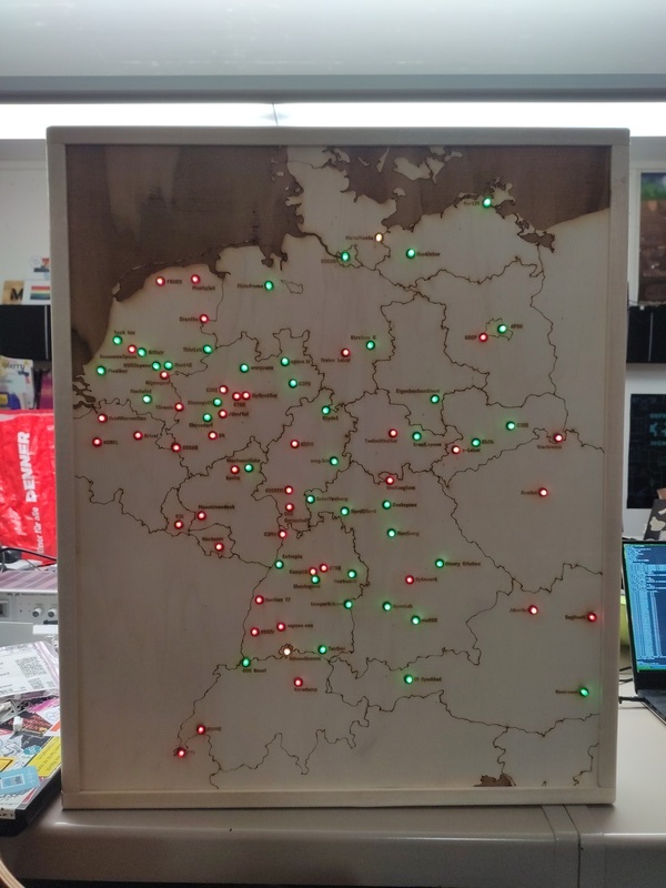
A map of hackerspaces lasercut from plywood, with their SpaceAPI opening states shown in red and green LEDs.
The LEDs are WS2812-compatible bulb-shaped LEDs, and they are controlled by an ESP32-C3 board.
This is a work in progress (2nd half 2024) project; documentation will be updated as the project progresses.
Contents of This Repository
erfamap-output/
The data for lasercutting the map was generated using a modified version of my Erfamap project, which uses the api.spaceapi.io SpaceAPI aggregator instead of the CCC internal Wiki to determine which dots to place where. A lot of this data was edited by hand in order to improve it for laser cutting.
spaceapi-info.jsonis the cache file used by the modified script. It has been edited manually to remove some entries which had broken or unsuitable API endpoints.map.svgis the output file generated by the modified script.map-prepared.svgis the file that has been prepared for laser cutting and engraving:- Labels have been move manually so that they are easier to assign to the correct LED, and so they don't overlap with any of the country borders.
- Text has been converted to paths.
- All paths have been assigned to layers corresponding to how they should be processed.
The modified Erfamap script will be released at a later point after some further cleanup.
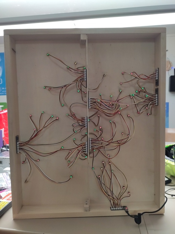
pcb/
The KiCad project for the PCBs that connect everything together.
Each PCB connects to 10 LEDs, and the PCB can be chained together to form a single WS2812 chain. There are 83 LEDs in the current version, so a total of 9 of these PCBs is required. The ESP32-C3 needs to be soldered to the first PCB.
⚠️ There is a small issue with V1.0 of the PCB! (Please check the version number on the silk screen!):
Pins 1 and 4 of the OUT pin header are swapped - this can be easily worked around by swapping wires number 1 and 4 in the JST connector plugged into this header.
esp32/
The PlatformIO Arduino project for the ESP32. It perfoms the following tasks:
- If no WiFi AP has been configured yet, it starts an AP on its own
- Connect to the AP (SSID:
spaceapimap, PSK:12345678) - Configure the WiFi network the ESP32 should connect to
- Connect to the AP (SSID:
- Connect to the WiFi network defined previously
- Obtain the current time through NTP
- Fetch the aggregated SpaceAPI responses from
api.spaceapi.ioand parse the JSON response - Update the WS2812 LEDs
The list of SpaceAPI endpoints to display is defined in esp32/src/spacemap.h.
The position of an endpoint in the spaces array corresponds to the index of the WS2812 LED it controls.
To compile and upload the code to the ESP32, use PlatformIO.
Using the PlatformIO Core CLI, upload should be as easy as this single command:
pio run -t upload
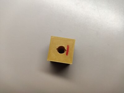
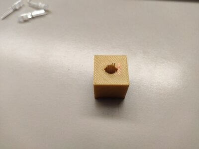
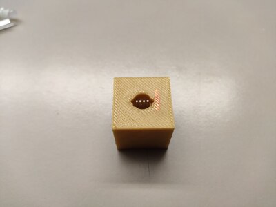
led_plugging_tool/
A 3D-printable tool that helps with cutting the LED legs to size and attach them to JST ZH-4 connectors the correct way.
Usage:
-
Print the tool on a 3D printer.
-
Put a LED bulb-first into the tool hole. Especially on first use, make sure that it's all the way in.
- The LED should only fit in one orientation.
-
Use a pair of wire cutters to cut the LED legs as close to the tool's surface as possible.
-
Take a cable fitted with JST ZH-4 connectors and push one connector firmly onto the LED legs inside the tool.
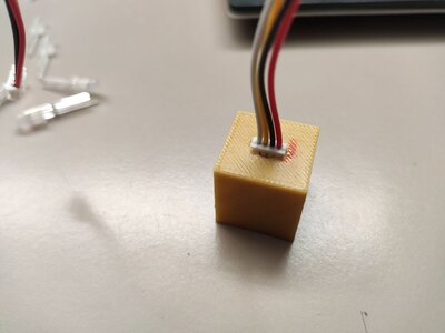
- The connector, too, should only (fully) fit in one orientation.
- You may need to bend the LED legs a little to get them to a pitch close enough to 1.5mm that the connector will slide on.
-
Pull the cable to remove the connector and LED from the tool.
-
Repeat steps 2-5 for every LED you need to prepare.
Components
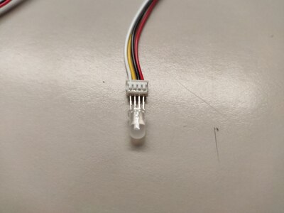
- WS2812-compatible 5mm bulb LEDs: https://de.aliexpress.com/item/1005005003701575.html
⚠️ The vendor appears to sell LEDs with different pinouts as the same product!
I recommend you order the LEDs before you order the PCBs so that you can make changes to the PCB if you receive a different pinout. The PCB design in this repo assumes the following LED pin order (starting from the flat side):
Dout,GND,5V,Din. - Black 5mm LED sockets: https://de.aliexpress.com/item/1005005062684329.html
- ESP32-C3 Super Mini: https://de.aliexpress.com/item/1005006252882434.html
- JST-ZH cables: https://de.aliexpress.com/item/1005007298855435.html (4P, Reversed)
- I recommend you order a mix of 100mm, 200mm and 300mm cables, as you'll be facing a variety of distances, and having shorter cables available makes for much easier troubleshooting.
- In my order, roughly 10% of the cables had a broken wire. Not sure whether I just got a bad batch, or whether they are just bad quality in general, but I recommend you keep that in mind when ordering.
- Don't rely on the order of colors in the product description. I've ordered different batches, and got differently color orders each time.
Additional Features
Enter Config Mode on Reset
- Solder a button or pin header between pins D5 and D6 on the ESP32-C3 Super Mini.
- These are the two pins closest to the USB port on the "unused" side of the ESP board.
- Press and hold the button or short the pin header with a jumper while you press the reset button.
- The ESP32 will now boot into WiFi config AP mode, where you can change the WiFi credentials and some additional parameters.
- If the configured WiFi can't be found, the ESP32 will automatically boot into config AP mode.
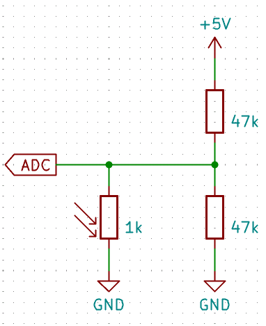
Automatic Brightness Adaption
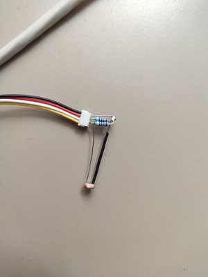
- You can plug a voltage divider with a photo resistor into the
INpin header on the PCB with the ESP32 on it, with the voltage divider's center tap connected to theDinpin. - You can use this to both adapt the LED brightness to the ambient light, and to turn off the LEDs below a certain ambient light level.
- The thresholds can be configured via the web interface in config AP mode (see above).
- Note that the brightness sensor readings are reversed: High values correspond to darker ambient light levels.
License
Unless otherwise noted, the contents of this repository are licensed under the MIT License (See LICENSE).
Public Domain Data
To the best of my knowledge, the contents of erfamap-output/ and esp32/src/spacemap.h are not protectable by copyright and are therefore in the public domain.
In case I do have copyright claims on them, I license these under the Creative Commons CC0 1.0 "No Rights Reserved" license.